top of page
Jonathan Perlman
LightsOut Smart Baseball
The project is my Senior Design Capstone Project for Pitt. We had the whole semester to take our sponsors idea and develop into into a working product for the next group to takeover. Due to the complexity of this project, I have attached a a slide show to show how our project developed. A link
Created with 3 other members from August to December 2020.
1
Click through this presentation to learn about the LightsOut Smart Ball!

2
If you played baseball growing up, you’ve heard your coach yell the infamous words: “get your glove down” or “keep your eye on the ball” countless times
This is because one of the most common errors a young infielder makes is taking their eye off the ball and not keeping their glove on the ground as the ball reaches them – resulting in the ball going under their glove.
Even major leaguers make this error – just ask Bill Buckner, who made this same mistake, and costed the Red Sox the 1986 World series win.

3
The main reason young players make this error is because they don’t focus completely on the ball the entire time. They worry about what to do with the ball after they get it, or who to throw it too, and end up never securing the ball in their glove.
This habit is extremely difficult to change, and requires learned repetition in order to become muscle memory.
This habit is extremely difficult to change, and requires learned repetition in order to become muscle memory.
4
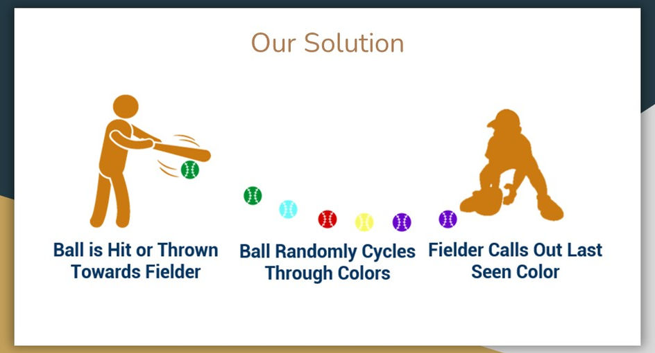
To address this, our team created the The Lights Out Smart Ball. The Ball’s objective is to offer a better way to learn proper fielding fundamentals by supplementing current training drills and methods.
The concept is simple, it’s a color changing smart ball that forces a fielder to focus on the ball at all times. In order to call out the correct colors as they appear, the fielder will have to keep their eye on the ball from the second it gets hit by the bat until the moment it enters their glove, thus proving to the coach that they remained focused, and reinforcing their habit of keeping your eye on the ball and keeping your glove down.
The ball will also have some additional functionality, such as calculating a player’s release time after fielding, but the main selling point is its ability to cycle random colors. To accomplish these objectives, our product will need to satisfy of requirements.
5
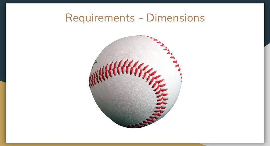
The first requirement is that our product must feel like a real baseball. We want our ball to be indistinguishable from a standard ball when players are fielding and throwing it. To ensure this, we needed to maintain the dimensions, weight, and center of mass of a baseball within a minimal tolerance. By doing this, users won’t feel a difference when training with our ball, and coaches can seamlessly integrate our product into their practices.
6
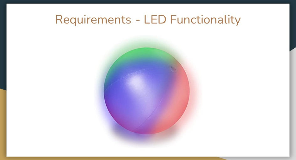
Next, the LEDs within the ball must function properly. The colors must cycle through random sequences each time the ball is used and the sequences should start when hit or thrown to the fielder and stop when it is received by the fielder.

7
Additionally, the housing of the ball must protect and secure all internal components from the impacts the ball will experience during training, such as getting hit by a bat, bouncing on the ground, or being thrown into a glove. The housing needs to be designed in a way where the components can be easily inserted into the ball and can be located centrally as to not throw off the center of mass.
8
Finally, the data tracking system must be able to accurately track the ball’s acceleration and send the data to a remote device via Bluetooth. This is important, because the acceleration data is used to dictate when to start and stop the LED sequence, as well as record the player’s catch-and-release time. Meeting these requirements and specifications will result in a product that optimizes training for the user and gives them a competitive advantage over their opponents.
9
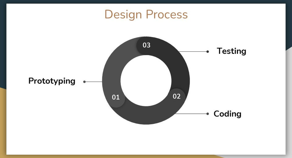
To design the Smart Ball, our design process can be broken up into 3 distinct portions: Prototyping, Coding, and testing.
10
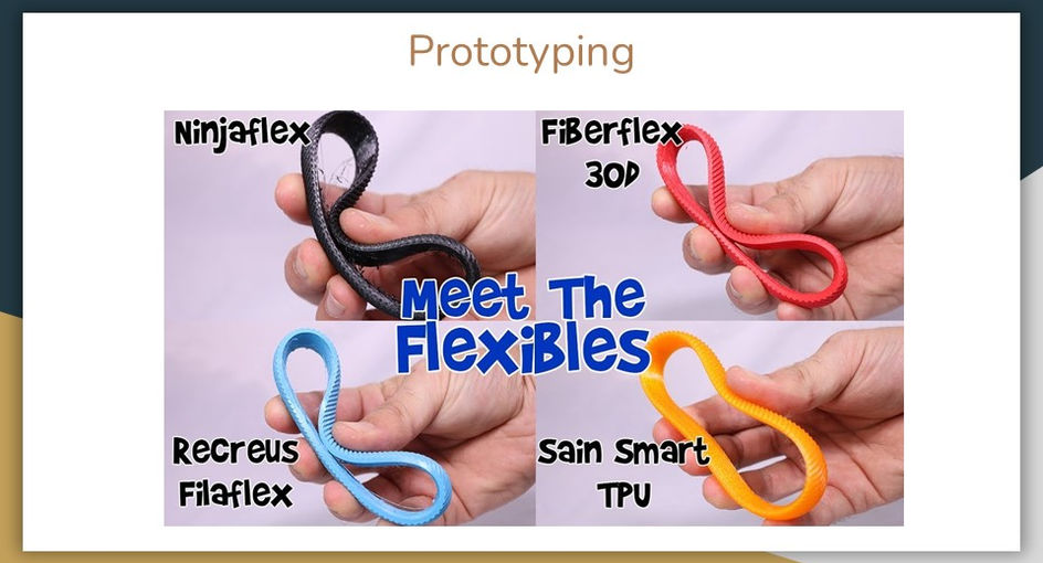
In regards to material selection, we knew we wanted to use a flexible filament, as they are durable and can create complex shapes, like our ball. We ended up choosing NinjaFlex (a TPU blend) as it can stretch 6 times its original length and return without deformation as opposed to 4. The NinjaFlex also distributes forces well, and from our testing was able to keep all the components safe, event when hitting it with a bat. It is also translucent which allows for the light to pass through.
Ultimate strength is 3.7 ksi or 26 Mega pascals
E = 1.8 kPSi = 12 Mega pascals
Ultimate strength is 3.7 ksi or 26 Mega pascals
E = 1.8 kPSi = 12 Mega pascals
11
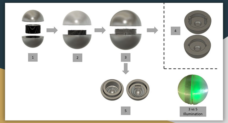
Most of our prototyping consisted of design iterations to the housing.
12
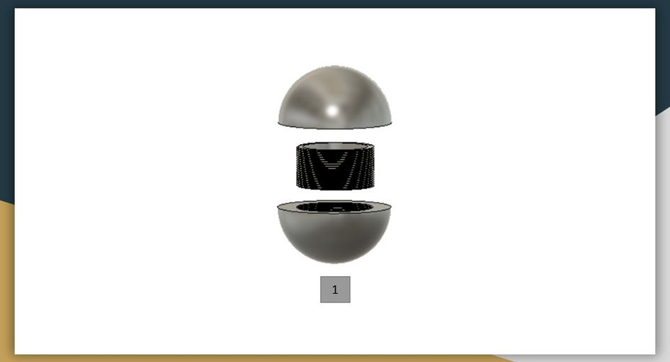
We began with a 3 part ball, 2 shells and a threaded center piece, after some testing we discovered a few concerns. The ball kept coming apart. After investigating further we attributed it to the threads. They were to small and led to a lot of translational slipping, basically the ball could be pulled apart easily.
13
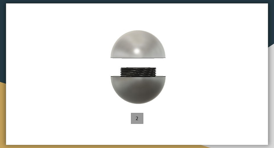
To countermeasure, we increased the thread size, and also reduced the complexity from 3 parts to 2. The ball performed much better, but still not up to our goal, so we decided to make the threads even bigger for the next iteration since we saw success initially. This ball also wasn’t illuminarting the best, so needed to address that concern too.
14
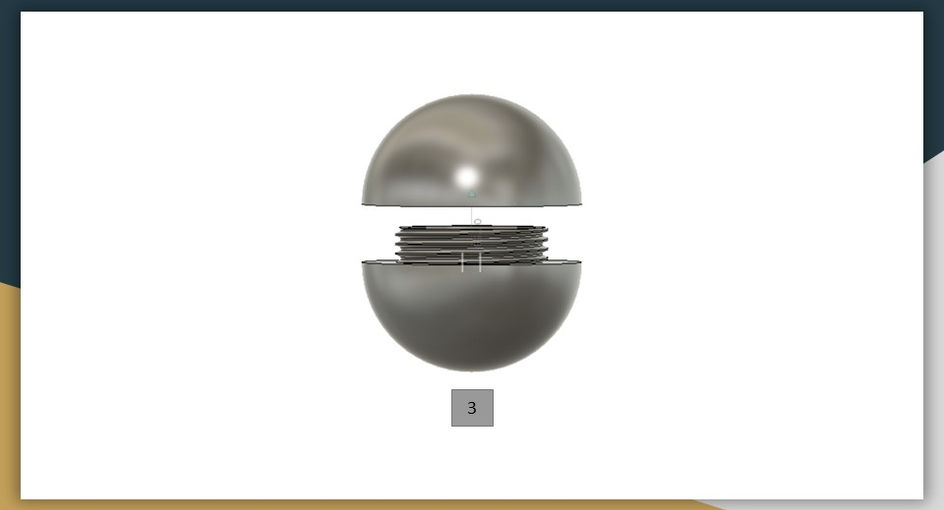
When we made the threads even bigger, new problems arose, the ball now had rotational slipping, making it easier to twist upon impact. So we now needed to find a happy medium between the number of threads and the thread size, as the bigger the thread, the less threads are present.
15
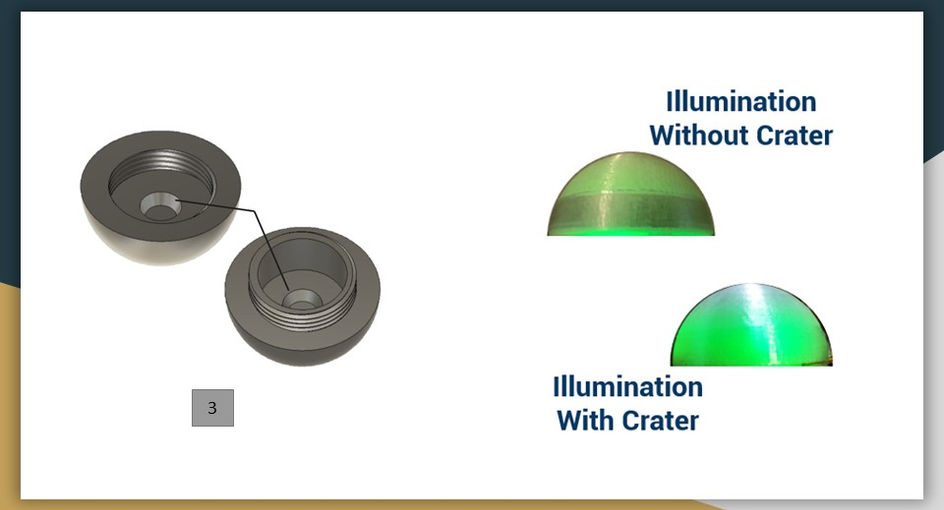
We did also add a crater in the shell to aid illumination. As you can see, the illumination did get better with this design chnage! It was at this point we also began to explore other methods to see if threads were really the best option.

16
This led to us to test a new design idea. We based this iteration on a twist lock mechanism similar to a medicine bottle. Ultimately, the design did not keep the ball secure, so we went back to our threaded concept.
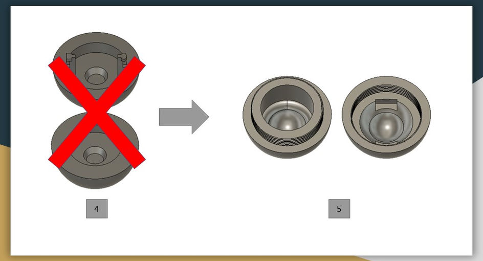
17
We finally settled on a threaded concept with a larger crater and grooves for the Arduino to rest.
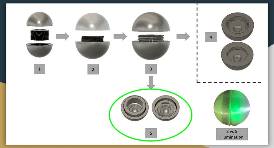
18
Leading to our final selection to be iteration number 5.
19
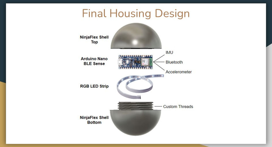
From those iterations we have arrived here, at our final housing design. Now on into the internal components and the code.
20
The next step in the design process was to somehow implement the intended functionality into the ball.
We chose to use an Arduino nano because of it's small size, programmability, Bluetooth capability, and it’s built-in IMU and accelerometer.
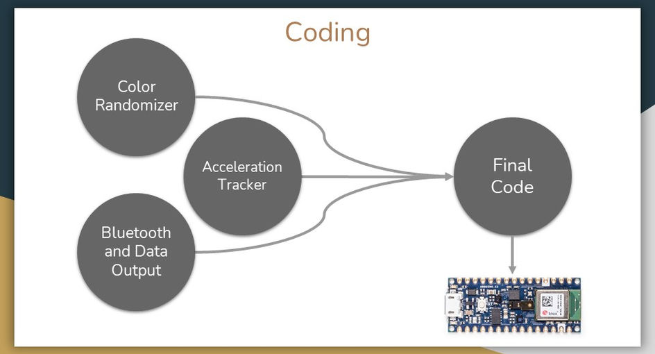
Our code is based on receiving three expected high acceleration events. The ball will start the sequence as green. The first high acceleration event is when the ball is hit or rolled out to the fielder, this will trigger a random sequence of lights that continues until the ball experiences the second high acceleration event when it is fielded. At this time, the ball will stop on the last color in that sequence and take a time measurement. The next acceleration event means that the ball has been thrown. When this happens, the Arduino will record a new measurement and take the difference between the two. This new variable is the release time and is sent to the connected Bluetooth device.
After the ball has been thrown, it will wait 5 seconds before flashing a red-blue-red sequence and return to green color, signaling that the release time has been sent and the sequence is ready to start again.
21
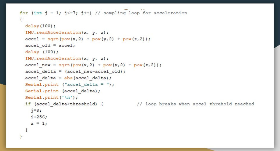
A key component in our code is our nested for loops. You can see from this screenshot of the code, every tenth of a second we poll the accelerometer for a new measurement.
If we measure two acceleration values that are different by a significant amount, we jump out of the randomizer loop and proceed to the next step of the sequence. We had experienced a lot of failed tests due to a slow sampling rate. This caused the accelerometer to miss high acceleration events and continue with the random sequence.
Since measuring the acceleration values was the most important part of proceeding with the code, it was vital that we developed a way to correct this issue.

22
Shown on this slide is the serial monitor of the Arduino which we were able to print values on to when testing our code. You can see that during one of our tests, we measured a release time of 2222, which is a value in milliseconds.

23
Using the Bluetooth capabilities of the Arduino and the nRF connect app on my phone, we were able to receive that value remotely.
Once you open the app and connect to our device, you can download the latest release time value by hitting the downward arrow. Right now, we are receiving the measurement in the form of a hex code that reads the two-bit values from right to left. You can easily convert that value to decimal form to get the correct value in milliseconds, but future groups can improve on this by figuring out a way to send it in decimal form.
Once you open the app and connect to our device, you can download the latest release time value by hitting the downward arrow. Right now, we are receiving the measurement in the form of a hex code that reads the two-bit values from right to left. You can easily convert that value to decimal form to get the correct value in milliseconds, but future groups can improve on this by figuring out a way to send it in decimal form.
24
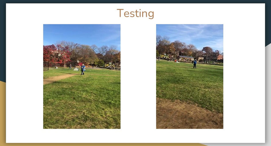
In these two videos, we tested our third iteration of the ball. We ran through a typical fielding practice routine. Due to a soldering error, the connection from the switch to the Arduino broke before we arrived at the field, so we were unable to test the functionality of the ball. However, we kept all the components inside the ball, and we were thrilled to see that the assembly withstood repeated impacts with the ground and the bat, even for choppers and line drives. Not to mention, it feels just like throwing a real baseball.
25
Here, we demonstrate the functionality of the ball. Each shake simulates a high acceleration event. The acceleration thresholds were set low for the sake of this demonstration and can easily be edited within the code.
bottom of page